
Overview
This section will focus on relationships between speed and edge quality, pump size, water nozzle and abrasive nozzle selection, maximum number of cutting heads and how some of these parameters can change over time.
Desired edge quality
Edge quality is defined with the numbers 1 through 5. Lower numbers indicate rougher edge finish; higher numbers are smoother. For thin materials, the difference in cutting speed for Quality 1 could be as much as 3 times faster than the speed for Quality 5. For thicker materials, Quality 1 could be 6 times faster than Quality 5. For example, 4” thick Aluminum Q5 would be 0.72 ipm (18 mm/min) and Q1 would be 4.2 ipm (107 mm/min), 5.8 times faster.
 Seperation Cut
 Through Cut
 Clean Cut
± 0.010"
 Good Finish
 Excellent Finish
± 0.005"
Pump specifications
Every waterjet company will be able to supply a chart similar to the following showing the horsepower, maximum pressure and maximum water output for the pumps offered with their systems.
| Pump Specifications | |||||
|---|---|---|---|---|---|
| Power | 30 HP (22 kW) | 50 HP (37 kW) | 75 HP (56 kW) | 100 HP (75 kW) | 150 HP 112 kW) |
| Max. Continuous Output Pressure | 60,000 psi (4137 bar) | ||||
| Max. Output Flow - Gallons/min (Liters/min) | 0.65 (2.46) | 1.1 (4.16) | 1.6 (6.06) | 2.2 (8.33) | 3.2 (12.1) |
Horsepower, pressure and water output
In order to achieve a required edge quality, cutting speed, tolerance and production requirement in a cost-effective manner, understanding the relationship amongst horsepower, pressure and water output is vital. These factors will determine the maximum size orifice you will be able to use, the maximum number of cutting heads you will be able to run, what speeds you will be able to cut at and the maximum thickness you will be able to cut cost effectively.
Horsepower
Waterjet pumps are specified in either horsepower (HP) or kilowatts (kW) to indicate the size of the electric motor that creates the force to pressurize the water. Engineers will size the hydraulic motor depending upon the water pressure and water output they are trying to achieve.
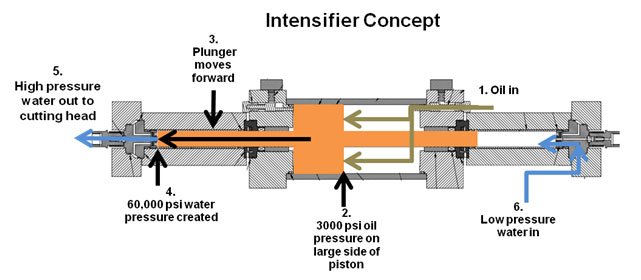
The most common pumps seen on the market today are intensifier style pumps. A simplified diagram of the intensifier concept is shown below. The pumps use hydraulics to apply a certain amount of oil pressure on one side of a piston of a certain diameter. On the water side of the pump, the diameter of the piston is much smaller. The difference in the surface area between the hydraulic side and the water side gives a multiplication factor, or intensification, to the pressure from the oil side. Most intensifier pumps have an intensification ratio of 20 times. This design will be explained in more detail in the “How it Works” chapter.
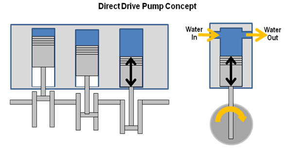
Another style pump sometimes used on waterjets is the direct drive pump. This pump uses an electric motor to turn a crankshaft that moves three or more pistons that create the water pressure, very similar to a car engine. Faster revolutions of the motor create higher pressure and more water volume. The basic concept for the direct drive is shown below.
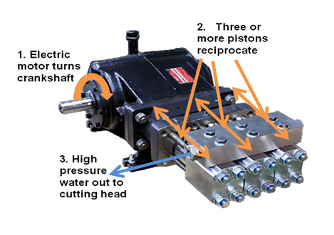
The horsepower between an intensifier style pump and a direct drive pump cannot be directly compared. Each style pump has benefits and drawbacks that must be evaluated based upon each user’s application.
The question frequently comes up as to which is better, a direct drive or an intensifier pump. Of course depending upon which manufacturer with which you are talking, you will get different answers. The best way to answer this is to ask the following questions and do your own research:
- What percentage of pumps in use today are intensifier as opposed to direct drive?
- What percentage of new machines being sold today have intensifier pumps versus direct drive?
- How many businesses have been created to swap out a direct drive pump with a retrofit kit to change over to an intensifier – basically dispose of the direct drive?
- How many businesses have been created to swap out an intensifier pump for a direct drive – in other words dispose of an intensifier pump?
- What are the maintenance costs associated with each style pump for the first 1500 hours, including replacement of consumable and spare parts?
- How much downtime is involved to replace consumable and spare parts on each style pump?
Pressure
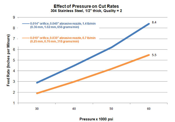
The pressure of the pump, measured in PSI, will determine cutting speeds for a given orifice size and number of heads. All other things being equal, there is an almost direct correlation between pressure and cutting speed; higher pressure results in higher cutting speeds. From a practical standpoint, increasing pressure also results in higher pump consumable costs, so that must be weighed against the faster cutting speeds.
The following graph shows the cutting speeds for ½” (12 mm) stainless steel for a Quality 2 edge finish. The two lines represent two common combinations of orifices and abrasive nozzles. In each case, doubling the pressure from 30,000 psi (2068 bar) to 60,000 psi (4137 bar) results in an increase in linear cutting speed of approximately 2.9 times.
IMPORTANT: Keep in mind that pump horsepower is not always a direct indication of maximum pressure for the pump. A 200 HP pump may not necessarily have higher pressure than a 100 HP or 50 HP pump.
Water output
Water output, or flow rate, is a function of horsepower and pressure. A 50 HP intensifier pump running at 60,000 psi will generally have a maximum output of 1 gallon per minute (gpm). A 100 HP pump running at 60,000 psi will typically put out 2 gpm. This information will help you determine the maximum number of cutting heads that you can use with a pump. Different pump manufacturers will produce slightly different volumes. They may also specify a Maximum Output Pressure and an Operating Output Pressure with different associated water outputs. It is important to verify that the water output specified is what you can expect on a regular production basis (i.e. flow rate based off of Operating Output Pressure).
Orifice selection – The scientific way
The Maximum Continuous Output Pressure and Maximum Output Flow from the “Pump Specifications” in Figure 1 are important in order to understand how many cutting heads you will be able to run with a pump. These numbers can be used in conjunction with the following “Flow Rate Through an Orifice” in Figure 2 to determine the number of cutting heads you can use.
Example 1: 50 HP Pump, 1 Cutting Head, 60,000 PSI, 1.1 GPM water output
- If you were looking at the 50 HP pump, from the “Pump Specification” chart you would know that your pump puts out 1.1 gpm at 60,000 psi.
- You would look down under the “60” column (corresponding to the 60,000 psi pump) in the “Flow Rate” chart until you found a number equal to or less than 1.1. In this case, you would end up at the cell with 1.00.
- You would then follow that row across to the left to see the maximum size orifice you could use for single-head cutting. In this case, the cell shows that a 0.014” would be the maximum recommended orifice for one head at 60,000 psi.
- If you were in a tight spot where you only had a 0.015” orifice you might be able to use it by running the pump at 55,000 psi.
| Orifice Diameter (inch) | |||||||||
|---|---|---|---|---|---|---|---|---|---|
| 20 | 25 | 30 | 35 | 40 | 45 | 50 | 55 | 60 | |
| 0.003 | 0.03 | 0.03 | 0.03 | 0.04 | 0.04 | 0.04 | 0.04 | 0.04 | 0.05 |
| 0.004 | 0.05 | 0.05 | 0.06 | 0.06 | 0.07 | 0.07 | 0.08 | 0.08 | 0.08 |
| 0.005 | 0.07 | 0.08 | 0.09 | 0.1 | 0.1 | 0.11 | 0.12 | 0.12 | 0.13 |
| 0.006 | 0.11 | 0.12 | 0.13 | 0.14 | 0.15 | 0.16 | 0.17 | 0.18 | 0.18 |
| 0.007 | 0.15 | 0.16 | 0.18 | 0.19 | 0.2 | 0.22 | 0.23 | 0.24 | 0.25 |
| 0.008 | 0.19 | 0.21 | 0.23 | 0.25 | 0.27 | 0.28 | 0.3 | 0.31 | 0.33 |
| 0.009 | 0.24 | 0.27 | 0.29 | 0.32 | 0.34 | 0.36 | 0.38 | 0.4 | 0.41 |
| 0.01 | 0.3 | 0.33 | 0.36 | 0.39 | 0.42 | 0.44 | 0.47 | 0.49 | 0.51 |
| 0.011 | 0.36 | 0.4 | 0.44 | 0.47 | 0.51 | 0.54 | 0.57 | 0.59 | 0.62 |
| 0.012 | 0.43 | 0.48 | 0.52 | 0.56 | 0.6 | 0.64 | 0.67 | 0.71 | 0.73 |
| 0.013 | 0.5 | 0.56 | 0.61 | 0.66 | 0.71 | 0.75 | 0.79 | 0.83 | 0.86 |
| 0.014 | 0.58 | 0.65 | 0.71 | 0.77 | 0.82 | 0.87 | 0.92 | 0.96 | 1 |
| 0.015 | 0.66 | 0.74 | 0.81 | 0.88 | 0.94 | 1 | 1.05 | 1.1 | 1.14 |
| 0.016 | 0.76 | 0.85 | 0.93 | 1 | 1.07 | 1.11 | 1.19 | 1.25 | 1.3 |
| 0.017 | 0.85 | 0.95 | 1.05 | 1.13 | 1.21 | 1.28 | 1.35 | 1.41 | 1.47 |
| 0.018 | 0.96 | 1.07 | 1.17 | 1.27 | 1.35 | 1.43 | 1.51 | 1.59 | 1.65 |
| 0.019 | 1.07 | 1.19 | 1.31 | 1.41 | 1.51 | 1.6 | 1.68 | 1.77 | 1.84 |
| 0.02 | 1.18 | 1.32 | 1.45 | 1.56 | 1.67 | 1.77 | 1.87 | 1.96 | 2.03 |
| 0.021 | 1.3 | 1.46 | 1.59 | 1.72 | 1.84 | 1.95 | 2.06 | 2.16 | 2.24 |
| 0.022 | 1.43 | 1.6 | 1.75 | 1.89 | 2.02 | 2.14 | 2.26 | 2.37 | 2.46 |
You would be at the 1.1 gpm limitation of the pump. If there were any water leaks in your system between the pump and the cutting head, you would likely have a pump “over stroke” situation where the pump would try to cycle too fast attempting to create the required pressure. With modern pumps, there is no harm done if this happens. The pump is simply shut down to protect itself from damage and an error message is displayed for the operator.
Running Two Cutting Heads
Example 2 50 HP Pump, 2 Cutting Heads, 60,000 PSI, 1.1 GPM water output
If you wanted to run 2 cutting heads, then you would take the 1.1 gpm number, divide it by 2 for a maximum of 0.55 gpm per head. Look for the cell under 60 kpsi that has a number smaller than or equal to 0.55. In this case, under the “60” column you would end up in the 0.51 cell, meaning that one 0.010” orifice would put out 0.51 gpm. The maximum number of heads that you could run with the pump at 60 kpsi would be two (1.1 ÷ 2 = 0.55. 0.55 > 0.51 = OK).
Orifice selection – the easy way
Since the pump design engineers have done most of the hard math already, most users need only refer to an “Orifice Selection Chart” similar to the following, which is usually supplied by the pump manufacturer. Here you would quickly see that for the 50 HP pump, you could use either one 0.014” orifice or two 0.010” orifices.
| Orfice Selection Chart | |||||
|---|---|---|---|---|---|
| Max # Orifices | 30 HP | 50 HP | 75 HP | 100 HP | 150 HP |
| 1 | 0.011 | 0.014 | 0.018 | 0.021 | 0.025 |
| 2 | 0.007 | 0.01 | 0.012 | 0.014 | 0.018 |
| 3 | 0.006 | 0.008 | 0.01 | 0.012 | 0.014 |
| 4 | 0.005 | 0.007 | 0.009 | 0.01 | 0.012 |
| 5 | 0.004 | 0.006 | 0.008 | 0.009 | 0.011 |
| 6 | 0.004 | 0.005 | 0.007 | 0.008 | 0.01 |
General pump selection guidelines
The next step in determining which pump is appropriate for your application is to determine the types of material you will be cutting and how many cutting heads you want to be able to run at one time.
If you are cutting parts out of foam, wood, cardboard or other soft materials, then you would be dealing with a pure water application. For pure water applications, a 30 HP pump is usually sufficient. As you can see from the previous Orifice Selection chart, up to three cutting heads could be used with 0.006” orifices.
If more cutting heads were needed, then a 50 HP pump could handle up to five cutting heads with 0.006” orifices.
For abrasive applications, the 50 HP is the general starting point. With this pump, you can run one head with a 0.014” orifice or two heads with 0.010” orifices. The 0.010” orifice will perform exceptionally well with respect to speed and cut quality on thinner material (1/2” and under).
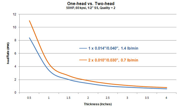
The following graph shows cutting speeds for single head versus dual head cutting in ½” stainless steel. As thickness get beyond 2” (50 mm), the absolute difference in cutting speeds between the nozzle combinations starts to decrease more dramatically.
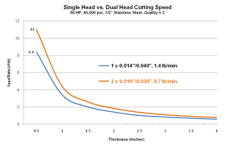
Cutting with two heads with 0.010” orifices effectively doubles the cutting speed (2 x 5.5 ipm) versus cutting with one head with a 0.010” orifice. Compared to cutting with one head with the 0.014” orifice, cutting with two heads will increase output by about 20 percent. To put this concept into real world terms, it would be like if you started cutting on a job on Monday morning with two cutting heads, then you could get it to your customer by Thursday afternoon. If you cut the job with one head, your customer wouldn’t get the part until Friday afternoon.
For someone looking to cut thicker materials on a consistent basis, then we would suggest allocating 50 HP per cutting head. If you selected a 100 HP pump, you could run two heads with 0.014”.
If you are cutting very small parts in high volumes, you might want a very large cutting table where you could run four cutting heads and quadruple your production over a single-headed system. In that case you would likely choose the 150 HP pump that can run four heads with 0.013” orifices.
Abrasive nozzle selection
As a general rule, the diameter of the orifice for the abrasive nozzle should be approximately three times the water nozzle orifice.
Some people would suggest using a smaller ratio, about 2.5 times. Using a smaller ratio does produce faster cutting speeds. The trade-off is increased nozzle wear and costs. Part tolerance will suffer because of the increased speed of nozzle wear.
Following is a quick reference guide for the most common orifices for abrasive waterjet cutting. Typical abrasive amounts and water flow are also shown for easy reference.
| Orifice (inches) | Abrasive Nozzle (Inches) | Abrasive Flow (lbs/min) | Water Flow @ 60 kpsi (GPM) |
|---|---|---|---|
| 0.01 | 0.03 | 0.65 to 0.7 | 0.51 |
| 0.011 | 0.03 | 0.8 | 0.62 |
| 0.012 | 0.03 | 0.9 to 1.0 | 0.73 |
| 0.013 | 0.04 | 1.4 | 0.86 |
| 0.014 | 0.04 | 1.4 | 1 |
| 0.015 | 0.04 | 1.5 | 1.14 |
| 0.016 | 0.04 | 1.6 | 1.3 |
Abrasive amount and cutting speeds
In Chapter 1, “Cutting Characteristics,” under the section “Creation of the abrasive waterjet stream”, we discussed how the abrasive waterjet stream is created. The cross-section of the cutting head is shown again here.
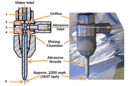
As abrasive is added to the waterjet stream, the abrasive particles are accelerated to near the speed of the waterjet, approximately 2200 miles per hour (almost three times the speed of sound). This speed imparts momentum to the abrasive particles so that they can erode the material. Adding more abrasive gives more energy to the process and erosion occurs faster. Eventually a saturation point occurs where adding more abrasive robs speed and power from the waterjet stream and cutting speeds will start to decrease. Each waterjet manufacturer goes through extensive testing with various orifice and nozzle combinations to find the optimum abrasive amount, balancing cost and cutting speed.
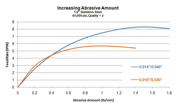
The following graph shows what happens to cutting speed for ½” stainless steel as abrasive is added. Speeds are shown for the two most common orifice/abrasive nozzle combinations, 0.010” orifice with a 0.030” abrasive nozzle (orange line) and 0.014” orifice with a 0.040” abrasive nozzle (blue line).
Starting with an abrasive flow of zero pounds per minute, there would be absolutely no penetration of the material except for maybe a very light etching of the top surface of the material. At this point cutting speed is zero. Cutting speed increases as more and more abrasive is added. For the larger nozzle combination, speed increases until around 1.5 pounds per minute. At this point, cutting speed starts to decrease as too much kinetic energy is removed from the waterjet stream by the abrasive. A similar thing happens with the smaller orifice/nozzle combination, but at slower speeds and lower abrasive amounts.
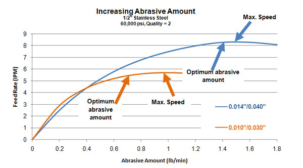
The optimum cost point may be slightly below what looks to be the apex of the speed curve. The “Law of Diminishing Returns” becomes evident. As the maximum speed is approached, each additional unit of abrasive that is added results in an ever smaller increase in speed. In the case of the orange line, increasing the abrasive from 0.7 pounds per minute to 1.0 pounds per minute yields an increase in speed of only 0.2 inches per minute. This 3.6% increase in speed results in a 4.7% increase in cost per inch.
Speed and efficiency of nozzle combinations
We can see in the following graph that larger orifice/abrasive nozzle combinations will cut faster than smaller combinations. With the larger nozzle combination, virtually all of the pump’s power is used, so it will cut faster. The smaller orifice/nozzle cuts slower because less total power from the pump is used.
Smaller orifice/nozzle combinations are more efficient though in their use of water and abrasive. The available power of the waterjet is concentrated into a smaller area, so more power is directed to the cut.
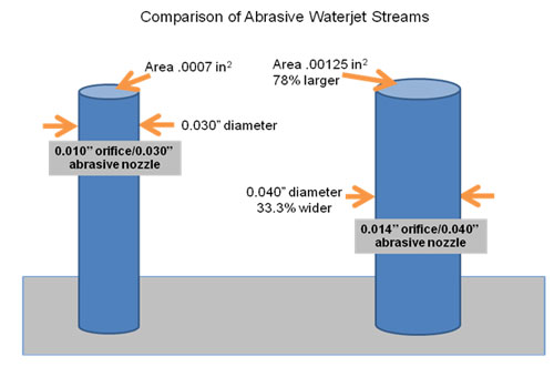
In the picture above, the diameter of the larger waterjet stream on the right is 33% wider and the area of this diameter is 78% greater. This makes the energy density lower than the smaller orifice/nozzle combination. The result is that, as shown earlier and repeated in the graph below, cutting with two 0.010”/0.030” heads is more cost-effective and productive than cutting with one 0.014”/0.040” head in thinner materials (approximately ½” and thinner).
Nozzle wear
As the abrasive nozzle wears, the diameter of the abrasive waterjet stream increases. The diameter increases by approximately 0.0001” per hour of cutting. Power per square inch is reduced. Therefore, the feed rate must be reduced in order to maintain the same edge finish, or the quality of the edge will deteriorate.
Cutting speed calculators
Various waterjet feed rate calculators are available online. With these calculators, you can play around with the various parameters to see how cutting speed and cost per inch are affected. Below is an example of one such calculator.
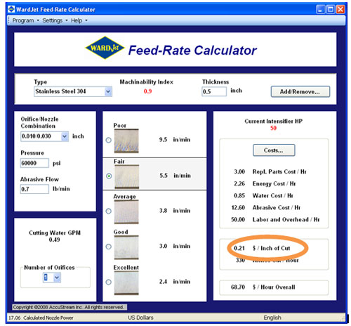
With all of these calculators, it is more important to focus on cost per inch (or foot, or meter), rather than cost per hour. Focusing on cost per foot takes into account the diminishing returns discussed in the previous section.
Another thing to keep in mind is that these calculators are only showing straight line cutting speeds. Depending upon part geometry, piercing times, machine design and more, actual part cutting times can vary significantly from just taking the total linear inches of cutting in a part and dividing that number by the inches per minute shown in a calculator. The calculators are useful though in at least getting an idea of speeds and costs.
Machinability Index
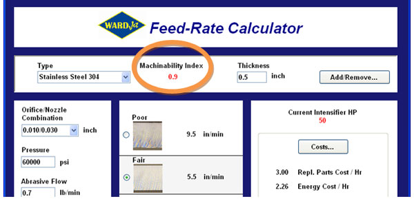
The Machinability Index shown in most waterjet feed rate calculators defines the relative cutting rates of different materials. Materials with higher numbers cut proportionately faster than lower numbers. Mild steel has a baseline value of one. Stainless steel at 0.9 would indicate that it cuts about 10% slower than mild steel to achieve similar edge quality and tolerance results.
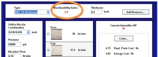
If you know the machinability indexes of two materials, you can estimate fairly easily a good cutting speed of one material from the other. We know that the Machinability Index of stainless steel is 0.9 and below we see that Aluminum’s Machinability Index is 2.9. You know that ½” stainless cuts at 5.5 ipm for the edge quality you want. You want to know the speed for ½” Aluminum. Divide the machinability of Aluminum by the machinability of stainless. 2.9 ÷ 0.9 = 3.2. Multiply the cutting speed for Stainless by 3.2 for the cutting speed in the same thickness of Aluminum. 5.5 ipm x 3.2 = 17.6 ipm. Therefore, 17.6 ipm would be a good place to start for ½” Aluminum.
Summary
In this chapter we looked at the three critical specifications of a high pressure pump: horsepower, pressure and water output. We reviewed how to figure out what size orifice to use based upon these pump specifications and how many cutting heads are being used. We covered the productivity increases and cost savings of using two smaller orifices versus one large orifice. Additionally, abrasive nozzle diameter selection was discussed in terms of the ratio to the orifice being used. Finally, we looked at waterjet feed rate calculators and how Machinability Indices can be used to extrapolate the cutting speed of one material from a different material.